Showing posts with label room. Show all posts

Tuesday, 10 October 2017

HMCS SACKVILLE Engine Room

Unlike today, where ships are typically powered by diesel or gas turbines, steam was the order of the day during the Second World War. Destroyers, cruisers, and battleships built during that time were fitted with steam turbines to provide better efficiency and higher speeds. Steam turbines are more expensive and are best fitted with gearboxes, so when it came time for emergency war-built convoy escorts - the Flower class, for instance - the Royal Navy decided to go with simple, reliable, triple expansion reciprocating steam engines. 

HMCS SACKVILLE.
A good example, and indeed the last of this particular powerplant in existence (though similar installations may exist in other museum ships), is the one in HMCS SACKVILLE on the Halifax waterfront. SACKVILLE is preserved by the Canadian Naval Memorial Trust (CNMT) as the world's last remaining Flower class corvette. I have photographed the interior of the engine room in SACKVILLE before, in 2002 and 2005, and wrote about it on the Hazegray and Underway website. Since that time, the engine room was allowed to deteriorate a bit, and it became quite dirty. More recently, former East Coast Fleet Chief ERA and CNMT trustee, Pat Devenish, has led an effort to clean up the engine room and return it somewhat to its former glory. Pat was kind enough to walk me through the engine room on Friday, so I could get a fresh set of photos for my records, and is responsible for many of the factoids that I recount in this post (though any errors are my own). 

Looking forward and to port, the cylinder tops are under the grey covers. Piston heads can be seen on the port wall over the engine. Everything has been scrubbed and repainted since I last set foot here. The blue plaque would not have been seen here during the war, but is apparently currently fitted within the engine rooms of HMC Ships.
The engine room has three levels, the highest being the catwalk on which I was standing to take the image above. Level 2 is on the catwalk visible at the bottom of the image, which brings you to the level of the cylinder heads and the original diesel generator and main switchboard. Below that, Level 1 brings you down to the propeller shaft and piston shafts. I'm not sure what the proper terminology is, but I hesitate to refer to them as decks.

Level 2

An original diesel generator, starboard side aft. The main switchboard is behind and to the right. The ladder descends from the catwalk over the aft end of the engine room. The genset's radiator is to the left of the photo.
The diesel generator provided electrical power for lights and other equipment requiring electricity, like radios and ASDIC (sonar). Diesel generators are still the method of choice for providing backup electrical power for modern facilities, with hospitals and sewage pumping stations as only two examples.

Close-up of the main switchboard, with what I assume is the generator's alternator in the foreground.
I doubt the electrical switchboard would meet modern safety standards, and the crew would have had to operate it in lively sea states in a type of ship that was itself known to be lively, and to "roll on wet grass". 

Looking aft from the port side, with the pistons to the right of the image. The ladder seen in the generator photo can be seen to the left of the image. The engine's condenser, which returned the steam to a liquid state before it returned to the boiler, is the grey object to the bottom right of the image. The catwalk at the rear of the photo is where visitors view the engine room from, as the rest of the space is not currently open to the general public.
The steam is first fed to the centre of the steam engine (when it is at its highest pressure), where the smallest of the four cylinders is located. The steam then passed to the mid-sized cylinder, and then to the two larger cylinders on the ends (when it is at its lowest pressure). A triple-expansion steam engine only needs three cylinders, but the final cylinder would have been too large for this installation, therefore it was split into two cylinders and SACKVILLE's engine has a total of four cylinders. Once the steam leaves the last cylinders, it passes to the condenser from where it returns to the boilers.

Ever wonder why railways were littered with water towers? Steam railway locomotives didn't have condensers, and needed to refill their tanks every once in a while. 

Another perspective of the engine room from the ladder in the forward port corner.

Looking forward and to port, the grey condenser is in the foreground. The pipes feeding into the top of the condenser come from the two cylinders on each end of the engine. Steam driven bilge pumps are in the background. I was standing on a Level 2 catwalk for this photo, looking down into Level 1.

Level 1

The steam driven bilge pumps seen in the background of the previous photo.

Not original to the engine room, the generator on the left provides ship's power during cold moves to and from the Dockyard and during memorial services off Point Pleasant Park on Battle of the Atlantic Sunday. On the right is the back end of the condenser. 

Looking aft along the starboard side of the engine. 

Looking into the engine from the starboard side. The connecting rods in the centre of the photo connect the piston rods above to the crank shaft at the bottom of the photo.

Looking forward at the row of piston and connecting rods through the engine.

Closeup of the connection between the piston rod above, the connecting rod, and the crank shaft below.

A view of the offset between the connecting rods from different cylinders - one is pushing down on the crank shaft, while the other rod is returned to top dead centre by the momentum of the shaft, ready for another power stroke. The piston rods traveled straight up and down, while the connecting rods are more dynamic in order to connect the piston rods to the rotating crank shaft. 
Where steam once powered the engine to turn the propeller shaft, SACKVILLE's propeller shaft is currently fitted with a hydraulic motor that when activated, turns the shaft and allows the engine to operate so that visitors can see it move.


Looking forward along the starboard side of the engine.

A closeup of the reversing engine and throttle handwheel.

Adjacent to the throttle handwheel is the engine room telegraph, which relayed orders from the wheelhouse.
Corvettes didn't exactly provide direct throttle control from the bridge to the engine room. Throttle settings and helm directions were relayed to the wheelhouse via voice pipe, one for each purpose (there was a voice pipe for the helmsman, one for the telegraph operator, and one for the throttle operator). And while the helmsman turned the wheel based on the direction from the bridge, another crewman listening to a separate voice pipe relayed throttle directions to the engine room via the telegraph, which in turn was registered on the telegraph in the photo above. With no less than 3 crew members involved in this chain, everyone had to be on their toes to ensure that throttle commands were relayed and obeyed in good order. Presumably this made coming alongside the jetty even more exciting than it is today.

Looking aft along the starboard side, showing the engine room telegraph opposite the throttle handwheel. The ladder back up to Level 2 is in the background.

This electrical distribution panel is located on the bulkhead at the aft end of the engine room. The ladder to the right accesses the "new" generator. Behind this bulkhead was the Engineer's Store.
Looking through my older set of photos, I see that the last time I stood in this location, I was the guest of former stoker Charles Dunbar. Charlie served in corvettes during the Second World War, and later went on to work for Foundation Maritime, where he joined Foundation Josephine in 1947.

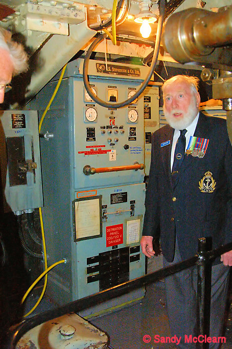
Charlie Dunbar in the engine room in 2005, standing in front of the same electrical distribution panel as the photo above.
Ten years later, I was present to see Charlie's ashes piped over the side of HMCS HALIFAX off Point Pleasant Park.

The ashes of Charlie Dunbar are piped over the side of HMCS HALIFAX.
SACKVILLE is an old ship, and desperately needs some time out of the water for urgent hull maintenance to be performed. The hull plating is getting thin, and some of the frames themselves are also rotten and in need of replacement. The photo below shows the state of the hull plating when left on its own - it isn't possible to control the humidity within the ship, and bare metal rusts. In the case of the S.S. Great Britain, the ship is kept dry in the graving dock in which she was built and the entire hull below the waterline is encased with a glass roof, and a sophisticated de-humidification system slows the progress of oxidation. That isn't currently possible with SACKVILLE - but it might be, if Battle of Atlantic Place is ever constructed. 

The aft starboard quarter of the engine room is the one spot that hasn't received attention yet, so of course I had to take a photo. The rusted plate in the centre of the image is hull plating.
Rivets are supposed to be flush with the inside of the hull plating, and these rivets are proud of the plate, suggesting erosion of the plating. Eventually, the plate will thin to the point that it is no longer structurally sound, assuming some of it isn't already there. The necessary maintenance is tentatively scheduled for the winter of 2017/2018. 

The photographic quality isn't as good, but I provide a better description of the workings in the engine room on the Hazegray and Underway website.


Saturday, 23 April 2016

HMCS TORONTO tour: Auxiliary Machinery Tour

My previous post on touring HMCS TORONTO covered the propulsion machinery spaces in both the forward and aft engine rooms. Forward and aft of these spaces are the AMRs, or Auxiliary Machinery Rooms. The primary inhabitants of these two rooms are four 850 kW Deutz MWM diesel generators that provide electrical power to the ship. 

It was an interesting opportunity to be able to photograph these two spaces, as the aft AMR was largely intact, while the forward AMR was in the process of being torn apart in preparation for being handed over to the Halifax Shipyard for refit.

Diesel generators intact inside their enclosures in the aft AMR. The enclosure is covered in access ports that can be opened to allow maintenance access all around each generator. The enclosure contains much of the sound produced by the generators, and is also useful in the event of fire.

Looking along the catwalk between the two generators. 
A memorial in the aft AMR for former crewmember who has "crossed the bar".

While the aft AMR was mostly intact, the forward AMR was in the process of being dismantled prior to refit.

In the forward AMR, the diesel engine inside the enclosure is exposed. 
Warships interiors are cramped, with every available space taken up by some piece of equipment - even the spaces below the deck plates. The bilge in the ship is often a treasure trove of lost tools that are lost by the ship's company during routine maintenance tasks, and they can't be retrieved until the ship is next stripped down prior to refit. As I recall, one of my tour guides was looking forward to retrieving a flashlight lost just weeks earlier.
The power generated in the two AMRs is routed to the rest of the ship to power everything from weapons systems, combat and navigation sensors, and the ship's hotel load (lights, etc) via two main electrical switchgear sets. 


Aft main switchgear.
The two AMRs don't just contain power generation equipment, but also have an assortment of other equipment as well. 

The AMRs also contain other equipment, such as R2D2 here (otherwise known as a fuel centrifuge for removing water and contaminants from the ship's fuel supply).
Another auxiliary machinery space, one deck below the weather deck and to the aft of the ship, is the "tiller flat" where the steering motors are found.

The steering gear is mounted on the rudder post. It is powered by two hydraulic motors, with the starboard steering motor seen to the left through the door.

The port hydraulic steering motor.


Friday, 8 May 2015

HMCS PRESERVER: Engine Room Tour (Updated with corrections)

At the time of writing this, only two steam-driven ships remain in the Royal Canadian Navy: HMC Ships PROTECTEUR and PRESERVER. Indeed, these Auxiliary Oiler Replenishment (AOR) vessels were the last two RCN ships designed and built with steam power, and shortly after they were commissioned the RCN introduced new surface warships with all gas turbine propulsion (IROQUOIS class), and later a combination of diesel and gas turbine propulsion (HALIFAX class). Similar ships to PROTECTEUR and PRESERVER built today are most likely diesel powered.

Being the last steam-powered vessel remaining in RCN service in Halifax, and soon to pay off and be discarded, I was keen on photographing PRESERVER's engine and boiler rooms for posterity. While I have done something similar for the Y100 steam plant in the ST. LAURENT and subsequent destroyers, the ships I toured had been out of service for several years, and my camera gear was somewhat deficient. This time around, the commentary won't be as good, but at least the photos will be better. 

Entering PRESERVER's engine room from the Machinery Control Room (MCR) (which itself will be covered in a later post), I was greeted by one of the largest open spaces onboard ship (second only, I think, to the helicopter hangar):

Engine room looking forward and to starboard from #2 Deck level.
The two grey items in the centre of the photo above are the low pressure (LP) and high pressure (HP) turbines, respectively. The astern turbine is mounted within the LP turbine casing, and on the same shaft. The grey shape to the bottom right (both forward and aft of the catwalk) is the double reduction gearbox. Immediately port of the LP turbine on #3 Deck (main level) are the two evaporators that make fresh water for the boilers (of which I have video, but no still photography for some reason). Aft of the gearbox are the two 1000 kW turbo alternators (steam driven generators). 

Another view from Deck #2, from further to starboard. The HP turbine is top left.
Another view from Deck #2, from further to starboard. The LP turbine to the right. The evaporators are behind the piping in the centre of the image.
A view looking directly down on top of the gearbox, giving a better idea of its size.
In the photo above, you can see the two shafts coming out of the two turbines, and connecting to the gearbox. A single shaft exits the gearbox along the ship's centreline, below the platform at the bottom of this photo, which connected directly to the propeller shaft. The reduction gearbox is required to transfer power from the high speed turbines to the propeller. Steam turbines are at their most efficient at relatively high revolutions per minute (RPM), while a ship's propeller is most efficient a much lower RPM. In this case, the gearbox also combines the power from the two turbines, and transmits it to a single propeller shaft.

After taking these photos, I descended the ladder to the left of the image to Deck #3, which is the main level of the engine room.

The Joy pump  compressor supplies control air. I don't remember what it does, apart from make noise.  
Port turbo alternator, looking aft and starboard.
Under normal conditions, electrical power is provided via the two 1000 kW turbo alternators, which are located port and starboard at the aft end of the engine room. These turbo alternators are self contained (they have their own condensers), although they receive steam from the main boilers. 

Port turbo alternator, looking aft and to port.
It was one of these turbo alternators in PROTECTEUR that caught fire while she was sailing off Hawaii in 2014, leading to her (slightly) early retirement. A lube oil line burst, sending a mist of 150 psi oil up into 500+ degree steam piping causing it to ignite. The fireball went forward in the engine room, hampering fire fighting efforts and attempts to shut off the oil supply. It was a very unfortunate event, and the crew did well to save the ship with no loss of life.

At times when steam is not available, auxiliary power is provided by a diesel generator, and a Solar gas turbine generator up forward on main deck level. This auxiliary power is necessary to start the boilers, and bring up enough steam to start the turbo alternators and main engine when bringing the steam plant online, after which the diesel and gas turbine generators can be shut down (and kept in reserve for emergencies). 

Errr....a dooflicky. Don't remember what this is Located immediately starboard of the HP turbine are the main engine air ejectors, which "...remove air and non-condensable gases from the main condenser to create and maintain main engine vacuum". The tank to the right, with the John Deere logo, is a deaerator. Get it? Deere? Oh, dear.
Looking forward over the tops of the two steam turbines.
You can get an idea, from the photo above, of the rat's nest of steam pipes connecting the boilers to the propulsion turbines and the turbo alternators, the turbines to the condensers, and back to the boilers. As in any aging powerplant, the piping can get old and brittle, and sometimes leaks or breaks. The difference with a steam plant is that not only do you have to worry about fuel and lube oil lines breaking, but you also have to worry about the steam lines. It was explained to me that a corn broom could be used to identify steam leaks - it is waved in the air around a steam line, and if there is a steam leak, the escaping high pressure steam (at up to 865 degrees at 600 psi) will cut the corn off the broom like a knife. It doesn't bear thinking about what that would do to human flesh.

The HP turbine looking forward and to port. The springs on top of the HP turbine are part of the auxiliary throttles.
The steam turbines are normally controlled from the MCR, however, local controls are provided for the turbines in case control from the MCR is lost. The auxiliary throttle station is located at the forward end of the HP turbine.

Auxiliary throttle station looking to starboard. The telegraph repeater is the circle to the left of the clock, below what appears to be a SHINCOM panel.
The auxiliary throttle station provided manual control to both steam turbines, as well as the astern turbine. The local telegraph reports throttle settings ordered from the bridge, independent of the telegraph in the MCR - presumably throttle settings could also be transmitted by other shipboard communications, including SHINCOM, in the event the telegraph was inoperative. There are two red pipe handles, one of which can be seen to the left of the image, which are used to control the auxiliary throttles. 

Auxiliary throttle, with one of the pipe handles installed. The grey rod attached to the base of the throttle handle, below the red rod, is normally hanging down, but is flipped up to attach to the throttle itself in this photo.
The operator at this station would operate the red handle to provide the required revolutions ordered from the bridge.

Looking down on the gearbox at the aft end of the HP turbine, to starboard and aft.

The double reduction gearbox, looking forward and to port.

The gearbox, looking forward and to starboard. The platform bridges the propeller shaft.
Immediately behind the catwalk over the shaft is the thrust block, which transmits the propeller's thrust to the hull and presumably prevents that thrust from affecting the shock mountings of the gearbox and turbines. 
It was at this point during the tour that a classic (in my mind, anyway) miscommunication occurred. Knowing that the old steam DDEs had a way of stopping the shaft from turning when the ship was being towed at low speeds, to prevent the turbines from being turned backwards (or when the auxiliary inflatable stern seal is in place, see below), I asked if they had a "brake". Misunderstanding me, my ever helpful guide replied that "Yeah, at 10:00, we have soup if you want." Apparently, it is actually known as a "lock", and is placed on the shaft when needed.

(As an aside, I did get soup in the wardroom during a "break" in my tour. It was french onion, and it was delicious.)

Looking forward along the propeller shaft, with the gearbox in the background. The plummer block is the grey object around the shaft.
Looking aft along the propeller shaft.
Having a deep displacement hull, and only a single shaft, the propeller shaft leaves the gearbox and travels maybe 30 feet to the stern seal, which can be seen in the background of the photo above, where the shaft passes through the bulkhead. In that 30 feet, the shaft leaves the gearbox, passes through the thrust block, a plummer block (which supports the weight of the shaft), and then the stern seal or stuffing box. In the case of the stern seal leaking, there is an inflatable auxiliary seal that can be installed, but only if the shaft is stopped and not turning.

With PROTECTEUR laid up after her fire, and PRESERVER similarly laid up due to hull corrosion issues, the RCN will likely never have another steam plant in operation - these were the last two. And this is largely a good thing, as modern gas turbines and diesel engines are more compact, lighter, have higher power to weight ratios, require less manpower to operate, and are generally less hazardous to the crew. That said, there will be former and serving Navy sailors (and my guides were good examples of the latter) who will miss these powerplants now that their page in the RCN history books has been turned.

(Updated on 21 May with corrections to some equipment descriptions, based on comments to my Facebook post.)

Saturday, 14 March 2015

HMCS IROQUOIS: propeller shaft & running gear

Following on from my earlier post with a tour of IROQUOIS' engine room, this post will trace the path of the propeller shaft after it leaves the gearbox. After departing the gearboxes, each propeller shaft passes through a thrust block (which transfers the thrust of the propeller to the hull) and several plummer blocks (which support the shaft along its length).

Looking down into the AMR. A yellow and black propeller shaft runs down the left side of the photo.
  Immediately aft of the main engine room, where the propulsion machinery is located, is the Auxiliary Machinery Room (AMR). The AMR houses three Solar Saturn 750 kW gas turbine generators plus one 1000 kW diesel generator, as well as numerous other pieces of smaller equipment. The port and starboard propeller shafts also pass through the AMR.

A propeller shaft (painted yellow & black) runs through the AMR heading aft (e.g. to the right).

Plummer blocks support the propeller shaft at the aft end of the AMR.
Due to the shape of the hull and there being two of them, the shafts must pass through not only the AMR, but also a DFO service tank, and finally the Gland Compartment before passing through the hull.

Starboard propeller shaft running through the Gland Compartment. I believe the blue hose is a hydraulic hose from the hydraulic pump for the CP props.
CP prop hydraulic pump unit.
Modern warships, including the IROQUOIS and HALIFAX classes, often use variable-pitch or controllable-pitch (CP) propellers, where the blades of the propeller can be rotated to different pitches. This is necessary because gas turbines can not be run backwards, and otherwise it might be necessary to include an extra "reverse" turbine on each shaft as was done with steam powerplants in the previous generation of warships. The CP prop allows the gas turbines to run in the same direction at all times, and the transition between forward and astern power is handled by the pitch of the propeller blades. The hydraulic pump that controls the pitch of the propeller blades is located in the Gland Compartment, two compartments aft of the AMR.

The starboard shaft passes through seals and exits the hull in the Gland Compartment.
The other side - the port shaft exits the hull.
Port propeller shaft intermediate support strut.

Port variable (or controllable) pitch propeller. A V-shaped strut supports the shaft just ahead of the propeller.

Starboard "running gear": the propeller shaft showing both intermediate and V-shaped support struts.
The original variable pitch propellers fitted to IROQUOIS and her sisters were only four bladed and were shaped differently (as I recall), and new propellers (presumably quieter and more efficient) were retrofitted at some point, possibly during her TRUMP refit in the early 1990s.

Update: The port variable pitch propeller, removed from HURON before she was sunk, is on display at the Naval Museum of Alberta in Calgary.