Unlike today, where ships are typically powered by diesel or gas turbines, steam was the order of the day during the Second World War. Destroyers, cruisers, and battleships built during that time were fitted with steam turbines to provide better efficiency and higher speeds. Steam turbines are more expensive and are best fitted with gearboxes, so when it came time for emergency war-built convoy escorts - the Flower class, for instance - the Royal Navy decided to go with simple, reliable, triple expansion reciprocating steam engines.
 |
| HMCS SACKVILLE. |
A good example, and indeed the last of this particular powerplant in existence (though similar installations may exist in other museum ships), is the one in HMCS SACKVILLE on the Halifax waterfront. SACKVILLE is preserved by the
Canadian Naval Memorial Trust (CNMT) as the world's last remaining Flower class corvette. I have photographed the interior of the engine room in SACKVILLE before, in 2002 and 2005, and wrote about it on the
Hazegray and Underway website. Since that time, the engine room was allowed to deteriorate a bit, and it became quite dirty. More recently, former East Coast Fleet Chief ERA and CNMT trustee, Pat Devenish, has led an effort to clean up the engine room and return it somewhat to its former glory. Pat was kind enough to walk me through the engine room on Friday, so I could get a fresh set of photos for my records, and is responsible for many of the factoids that I recount in this post (though any errors are my own).
 |
| Looking forward and to port, the cylinder tops are under the grey covers. Piston heads can be seen on the port wall over the engine. Everything has been scrubbed and repainted since I last set foot here. The blue plaque would not have been seen here during the war, but is apparently currently fitted within the engine rooms of HMC Ships. |
The engine room has three levels, the highest being the catwalk on which I was standing to take the image above. Level 2 is on the catwalk visible at the bottom of the image, which brings you to the level of the cylinder heads and the original diesel generator and main switchboard. Below that, Level 1 brings you down to the propeller shaft and piston shafts. I'm not sure what the proper terminology is, but I hesitate to refer to them as decks.
Level 2
 |
| An original diesel generator, starboard side aft. The main switchboard is behind and to the right. The ladder descends from the catwalk over the aft end of the engine room. The genset's radiator is to the left of the photo. |
The diesel generator provided electrical power for lights and other equipment requiring electricity, like radios and ASDIC (sonar). Diesel generators are still the method of choice for providing backup electrical power for modern facilities, with hospitals and sewage pumping stations as only two examples.
 |
| Close-up of the main switchboard, with what I assume is the generator's alternator in the foreground. |
I doubt the electrical switchboard would meet modern safety standards, and the crew would have had to operate it in lively sea states in a type of ship that was itself known to be lively, and to "roll on wet grass".
 |
| Looking aft from the port side, with the pistons to the right of the image. The ladder seen in the generator photo can be seen to the left of the image. The engine's condenser, which returned the steam to a liquid state before it returned to the boiler, is the grey object to the bottom right of the image. The catwalk at the rear of the photo is where visitors view the engine room from, as the rest of the space is not currently open to the general public. |
The steam is first fed to the centre of the steam engine (when it is at its highest pressure), where the smallest of the four cylinders is located. The steam then passed to the mid-sized cylinder, and then to the two larger cylinders on the ends (when it is at its lowest pressure). A triple-expansion steam engine only needs three cylinders, but the final cylinder would have been too large for this installation, therefore it was split into two cylinders and SACKVILLE's engine has a total of four cylinders. Once the steam leaves the last cylinders, it passes to the condenser from where it returns to the boilers.
Ever wonder why railways were littered with water towers? Steam railway locomotives didn't have condensers, and needed to refill their tanks every once in a while.
 |
| Another perspective of the engine room from the ladder in the forward port corner. |
 |
| Looking forward and to port, the grey condenser is in the foreground. The pipes feeding into the top of the condenser come from the two cylinders on each end of the engine. Steam driven bilge pumps are in the background. I was standing on a Level 2 catwalk for this photo, looking down into Level 1. |
Level 1
 |
| The steam driven bilge pumps seen in the background of the previous photo. |
 |
| Not original to the engine room, the generator on the left provides ship's power during cold moves to and from the Dockyard and during memorial services off Point Pleasant Park on Battle of the Atlantic Sunday. On the right is the back end of the condenser. |
 |
| Looking aft along the starboard side of the engine. |
 |
| Looking into the engine from the starboard side. The connecting rods in the centre of the photo connect the piston rods above to the crank shaft at the bottom of the photo. |
 |
| Looking forward at the row of piston and connecting rods through the engine. |
 |
| Closeup of the connection between the piston rod above, the connecting rod, and the crank shaft below. |
 |
| A view of the offset between the connecting rods from different cylinders - one is pushing down on the crank shaft, while the other rod is returned to top dead centre by the momentum of the shaft, ready for another power stroke. The piston rods traveled straight up and down, while the connecting rods are more dynamic in order to connect the piston rods to the rotating crank shaft. |
Where steam once powered the engine to turn the propeller shaft, SACKVILLE's propeller shaft is currently fitted with a hydraulic motor that when activated, turns the shaft and allows the engine to operate so that visitors can see it move.
 |
| Looking forward along the starboard side of the engine. |
 |
| A closeup of the reversing engine and throttle handwheel. |
 |
| Adjacent to the throttle handwheel is the engine room telegraph, which relayed orders from the wheelhouse. |
Corvettes didn't exactly provide direct throttle control from the bridge to the engine room. Throttle settings and helm directions were relayed to the wheelhouse via voice pipe, one for each purpose (there was a voice pipe for the helmsman, one for the telegraph operator, and one for the throttle operator). And while the helmsman turned the wheel based on the direction from the bridge, another crewman listening to a separate voice pipe relayed throttle directions to the engine room via the telegraph, which in turn was registered on the telegraph in the photo above. With no less than 3 crew members involved in this chain, everyone had to be on their toes to ensure that throttle commands were relayed and obeyed in good order. Presumably this made coming alongside the jetty even more exciting than it is today.
 |
| Looking aft along the starboard side, showing the engine room telegraph opposite the throttle handwheel. The ladder back up to Level 2 is in the background. |
 |
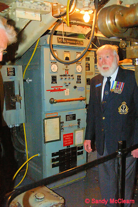
| This electrical distribution panel is located on the bulkhead at the aft end of the engine room. The ladder to the right accesses the "new" generator. Behind this bulkhead was the Engineer's Store. |
Looking through my older set of photos, I see that the last time I stood in this location, I was the guest of former stoker Charles Dunbar. Charlie served in corvettes during the Second World War, and later went on to work for
Foundation Maritime, where he joined
Foundation Josephine in 1947.
 |
| Charlie Dunbar in the engine room in 2005, standing in front of the same electrical distribution panel as the photo above. |
Ten years later, I was present to see Charlie's ashes piped over the side of HMCS HALIFAX off Point Pleasant Park.
 |
| The ashes of Charlie Dunbar are piped over the side of HMCS HALIFAX. |
SACKVILLE is an old ship, and desperately needs some time out of the water for urgent hull maintenance to be performed. The hull plating is getting thin, and some of the frames themselves are also rotten and in need of replacement. The photo below shows the state of the hull plating when left on its own - it isn't possible to control the humidity within the ship, and bare metal rusts. In the case of the S.S.
Great Britain, the ship is kept dry in the graving dock in which she was built and the entire hull below the waterline is encased with a glass roof, and a sophisticated de-humidification system slows the progress of oxidation. That isn't currently possible with SACKVILLE - but it might be, if
Battle of Atlantic Place is ever constructed.
 |
| The aft starboard quarter of the engine room is the one spot that hasn't received attention yet, so of course I had to take a photo. The rusted plate in the centre of the image is hull plating. |
Rivets are supposed to be flush with the inside of the hull plating, and these rivets are proud of the plate, suggesting erosion of the plating. Eventually, the plate will thin to the point that it is no longer structurally sound, assuming some of it isn't already there. The necessary maintenance is tentatively scheduled for the winter of 2017/2018.
The photographic quality isn't as good, but I provide a better description of the workings in the engine room on the
Hazegray and Underway website.